|
|
请使用QQ关联注册PLM之家,学习更多关于内容,更多精彩原创视频供你学习!
您需要 登录 才可以下载或查看,没有账号?注册

x
有两种方式可以创建草图:) ^* J/ o; u+ e
1.通过参考平面创建
3 H5 d1 j% d. w. B//获得参考平面, I5 V' ]! c! c/ K
CATLISTV(CATISpecObject_var) spRefPlanes = spPart->GetReferencePlanes();
5 x* h5 z0 C% z+ ~; }% K( S//初始化草图工厂1 H; Z2 f4 Q- {7 c. o2 A' F
CATISkeTChFactory_var spSketchFactory(spContainer);: K0 g+ @$ j! l6 K
//在XY plane 上创建草图* G( C7 b& x Z: L9 R+ q" r
CATISketch_var spSketch = spSketchFactory->CreateSketch(spRefPlanes[1]));# a# G# [4 t3 _/ z" w& v
2.通过原点和两个矢量方向$ f; d9 [4 q* ]) ^, j( K2 v9 j/ u0 [6 _
该方法通过定义一个原点和两个方向 pH、pV 进行创建。" T1 W, S* E* ~# m4 d0 W+ C+ g
定义原点和方向:. `; z$ D' Y" x8 P1 D
double pOrigin[3]={0,0,10};' L6 X+ q! h7 v! _' O
double pH[3]={1,0,0};, |, `6 }) G2 u
double pV[3]={0,1,0};
: ~9 g; O) U6 I4 |& e- KCATISketchFactory_var spSketchFactory(spContainer);
; z6 j( N1 p8 I% S+ ICATISketch_var spSketch = spSketchFactory->CreateSketch(pOrigin, pH, pV);6 h% U5 u0 H6 y! V* m# H7 T
K6 a: I1 `: D9 w" Q# {. j
; A" h5 W" b. i$ m6 C0 t7 y
sp2DFactory(spSketch);. a, D6 d! F9 Z) ?6 Z
//下面创建点
7 C7 a; l8 Y0 X" v7 z& c2 c% Q0 HCATI2DPoint_var spPt_bottom_left, spPt_bottom_right, spPt_top_right, spPt_top_left;; u* ?2 s9 a9 U
double pt_bottom_left[2] = {10, 10};
) ~4 y( G: f8 \ U! jdouble pt_bottom_right[2] = {50, 10};1 D8 q0 V$ I$ a" _
double pt_top_right[2] = {50, 50};
0 y2 m _3 |" J9 }( s3 k& n; ]double pt_top_left[2] = {10, 50};8 j( Q# a8 B5 l, N' y4 d3 [+ K
spPt_bottom_left = sketch2DFactory->CreatePoint(pt_bottom_left);* z! C$ h0 ?, y# }; J
spPt_bottom_right = sketch2DFactory->CreatePoint(pt_bottom_right);8 b: g0 [4 U# P9 i: Z; Y0 B% C9 V& j
spPt_top_right = sketch2DFactory->CreatePoint(pt_top_right);
k- r1 y# ~' D8 Z' V% FspPt_top_left = sketch2DFactory->CreatePoint(pt_top_left);
$ X% g- ~" Q& d" B, }( H6 H//开始创建线0 P) {1 k( n4 W) \, [8 f( o+ w
CATI2DLine_var spLine1, spLine2, spLine3, spLine4;
0 G, n7 x5 X9 I7 M! YspLine1 = sketch2DFactory->CreateLine(pt_bottom_left,pt_bottom_right);9 {9 U; Y6 b+ Y* t6 E8 U& I
spLine2 = sketch2DFactory->CreateLine(pt_bottom_right,pt_top_right);7 h/ \ y7 h" |0 z* m$ q0 U
spLine3 = sketch2DFactory->CreateLine(pt_top_right,pt_top_left);$ l5 X0 |( H; V. T' n6 z
spLine4 = sketch2DFactory->CreateLine(pt_top_left,pt_bottom_left);( ], v; s. z X, f
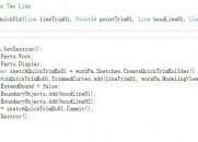
//将线的首尾连接起来& S! w7 j0 h I- ]8 k% u1 H3 W
1 \ g: Q: e: n9 l+ Y
CATI2DCurve_var spCurve1 (spLine1);
$ H# U% P& Z: O. {CATI2DCurve_var spCurve2 (spLine2);# |3 a3 M& S- G1 O8 [
CATI2DCurve_var spCurve3 (spLine3);
( s7 b+ h k, o* S# ]CATI2DCurve_var spCurve4 (spLine4);
( ?" P: W& C& X! u$ SspCurve1->SetStartPoint(spPt_bottom_left);* P3 d; @4 Z- H: H* R
spCurve1->SetEndPoint(spPt_bottom_right);! x; U& ~# M8 T9 N) V2 Y& [
spCurve2->SetStartPoint(spPt_bottom_right);
! N! t" ^4 K4 r) sspCurve2->SetEndPoint(spPt_top_right);
2 s. T2 o& |9 A- L7 BspCurve3->SetStartPoint(spPt_top_right);$ W$ u5 p7 p6 E& b, d$ n
spCurve3->SetEndPoint(spPt_top_left);
* r* ?2 I: L4 u! Y: rspCurve4->SetStartPoint(spPt_top_left);
5 W9 m- D( W9 y1 l. L5 zspCurve4->SetEndPoint(spPt_bottom_left); y$ K/ y4 D. |8 H( l8 Q# ^
//然后退出草图:9 g" M: z) X$ N% i- B5 p
spSketch->CloseEdition();
5 s. \- ^7 N6 ?% C. ~1 D9 `4 O9 M& ^6 v7 w. P" h1 g( q
$ [) B! l, T1 e4 t% X! a
, ~7 g5 y# x2 j+ V# h创建草图约束 B9 T8 ^. V- z, S
CATI2DConstraintFactory_var spConstraint2DFactory(spSketch);
& R1 ?$ m( F; D. z9 ~//定义spLine1 为水平约束2 J/ X, u8 ~- X: _
spConstraint2DFactory->CreateConstraint( spLine1, NULL, NULL, NULL, NULL, NULL,4 a/ X; k) N. y/ O3 V) c
NULL, Cst2DType_Horizontal, 0, 0 );
' I) @' o$ r) v& w- x5 x. z" a+ U//定义spLine2 为垂直约束
6 o: t. {* P$ cspConstraint2DFactory->CreateConstraint( spLine2, NULL, NULL, NULL, NULL, NULL,, h6 Q- D" u! w- F' Z! P0 e
NULL, Cst2DType_Vertical, 0, 0 );
& q4 k9 i; g* i. k//定义spLine3 为水平约束- ^( B8 }: Q/ Q- i# U. f3 f
spConstraint2DFactory->CreateConstraint( spLine3, NULL, NULL, NULL, NULL, NULL,
: X4 Z& `, Q) m5 [5 m) b3 Q/ pNULL, Cst2DType_Horizontal, 0, 0 );
$ ?) h J0 B, N5 q$ p( t4 m* W2 w//定义spLine4 为垂直约束* x8 C' ^1 ?# N/ n* n
spConstraint2DFactory->CreateConstraint( spLine4, NULL, NULL, NULL, NULL, NULL,' ]: c- E4 I. c' h$ x; e0 z! C5 ~
NULL, Cst2DType_Vertical, 0, 0 );9 W2 `" i6 f, {' j+ |) [7 T x1 X
//定义spLine2 的长度约束% Z' X8 U! Q) i% g
spConstraint2DFactory->CreateConstraint( spLine2, NULL, NULL, NULL, NULL, NULL," T! P* ~9 U* q; m# i
NULL, Cst2DType_Length, 0, 0 );
! @8 _ P# G, G7 I0 k% M% S t+ b% h2 g3 t+ v
//定义spLine2 与spLine4 的距离约束
6 I: h# y4 G' @# m2 Q; RspConstraint2DFactory->CreateConstraint( spLine2, NULL, spLine4, NULL, NULL, NULL,1 h: z4 k8 Y5 u# }4 _: {, k
NULL, Cst2DType_Distance, 0, 0 );7 E3 B' i0 K6 j$ d7 b
//定义spPt_bottom_left 与X 轴的距离约束
. m) |: a! L% D0 a; R3 k3 dCATI2DAxis_var spSupport = NULL_var;
/ `: ~ e* K0 B' p# espSketch->GetAbsolute2DAxis(spSupport);: g5 k& x' w; p+ Y1 Y
spConstraint2DFactory->CreateConstraint( spPt_bottom_left, NULL,
9 q3 h+ z0 @5 K% G2 f E7 i# GspSupport->GetHDirection(), NULL, NULL, NULL, NULL,Cst2DType_Distance, 0, 0 );
" I: @' Z2 S6 i/ Z, A7 Y3 ~" c2 F F//定义spPt_bottom_left 与Y 轴的距离约束
$ M( i, p" A) s% u* KspConstraint2DFactory->CreateConstraint( spPt_bottom_left, NULL,8 {7 E8 {4 O: ~: o! P1 g/ x
spSupport->GetVDirection(), NULL, NULL, NULL, NULL,Cst2DType_Distance, 0, 0 );6 ?1 B6 P2 v6 v1 d9 c2 a2 _
/ I; ?2 v0 ]' T7 T; F5 E }
' W. B l: D: c* o: F; Q |
|


 [复制链接]


 |小黑屋|PLM之家-专注工业软件生态建设,大模型CAD创新生态


 发表于 2018-2-22 13:25:32