|
|
请使用QQ关联注册PLM之家,学习更多关于内容,更多精彩原创视频供你学习!
您需要 登录 才可以下载或查看,没有账号?注册
x
Manufacturing Process Management basic tasks
( ^8 o6 f6 l9 m3 d% f e, V9 J! ^; Q! A. M7 l* a7 A2 X% F2 R8 c
To create a manufacturing process plan, you can perform the following basic
! T: P! D5 u! ctasks in the Manufacturing Process Management environment.
6 x* N( b3 L( C7 _( Q* o, ^$ T& }9 j2 C: l9 Y7 J
• Create a manufacturing process. E0 J k7 ~- G' n
The manufacturing process plan includes a top-level structure of the/ l' _7 d/ x* z" S! ], v0 P
process needed to manufacture the product, as well as a detailed design
0 B8 W5 @; s% P5 N7 B$ ^of the individual processes and activities to be included in the plan. As$ p! X+ X) p8 F' _" _
you build the process structure, you can assign resources to the various
! b, o: |( r) M4 s2 L; {. fprocesses, operations, and activities. You can also identify the specific
9 A7 h3 [6 d4 o$ [0 D8 Plocations within the plant where each operation and activity is performed.
) c" N0 w5 I& r2 I+ P) k
/ d, J2 R! D8 u3 V4 Y8 Lo Load the product and the work area.
8 B& o' f; u/ Q. [5 c6 `o Create the process structure8 {1 ~& }9 t7 c( o. f8 C( I
o Create operations, t0 R. W; I R
o Establish relationships between process, product, and work areas3 L2 \4 a7 O0 Z4 ]0 S* G6 x
o Assign work areas
e9 ]. J$ `0 F% b) e& |o Create activities under operations/ H! L- ^6 |8 O7 g6 L4 x1 ?1 z% A
o Add resources to operations# y* b# h) s) J# V
o Verify the manufacturing process
2 d& |$ J7 }* R2 J! C% E$ e3 U3 h4 j4 Ho Create structures with Microsoft Excel™/ f$ [' ]* R- p% T9 _3 W7 x" x
/ h' V6 |0 C. T) N# w# g. d• Create a factory or plant structure
$ m* X9 m/ W; U a+ Y! CPlant Designer allows you to design, modify, import, and export the
% n% y7 m( G" T. r Lstructure of the factory in which you build the product. You can provide+ m7 e$ I( c1 E: R$ f2 \
a view of the plant structure layout and organize the areas where the9 _" t+ }7 }6 l( U
product is manufactured and assembled.& O Z+ a. e0 E0 _" t
o Create and edit the plant structure
/ w3 Y; n: `9 Ro Define work areas2 w& t5 Y4 t+ W3 B3 }( I
o Manage plant structures and layouts
% s! Z( k% l7 U; M" g, mo Store model files in DWG format or as JT files for visualization1 @- T7 K, J* h3 V
X& [* u7 f9 K' v3 e• Create a preliminary data indicator (baseline)! v* D; z( Z/ F
You can create a preliminary data indicator (PDI) or baseline of a
& h( g( P3 h8 X* T- d! S9 vmanufacturing process that is in development. You can then release
9 q# X6 {1 C. Z8 P# S* athe PDI to other users and external suppliers, who can then complete
/ _) d- F; N7 o* q8 k$ cassociated work on the basis of the data in the PDI. You would normally8 U5 c* o: q5 ~) R- _% s, G. a
release PDIs at defined intervals, so that users know the effectivity of
* w& a" C+ R; y; {. g" Q, S+ P$ Ithe data provided.4 J1 N0 ]- z# L* D
& F4 m% p/ V8 D# n% ?$ @) G+ Y( |• Create an intermediate data capture
6 c* t" J6 {! d$ s. e: yYou can capture the state of any structure or part of a structure for
6 Z& u& o6 S2 msubsequent retrieval and viewing. This capture data does not represent
9 z$ z, @6 Z2 B$ w8 M# ], l4 n, o+ Athe final released state of the structure, so it is referred to as an
# c, f6 F# D Y1 h' qintermediate data capture (IDC). The configuration rules are saved- ?: p: W2 h7 J' n1 O
with the structure allowing its exact state at the time of capture to be
; |1 A8 U& {. e! N/ b6 p3 Oreproduced each time it is retrieved. Creating an IDC does not affect any
~+ M! j3 F2 c; a, G" tsubsequent changes to the structure or its release by a Workflow process.
% C$ V) }* a R9 Q* o2 f
2 m) I/ l8 |; l L) M• Create reports
5 q, m6 v/ ^5 b+ |& | KYou can create reports in the rich client or the thin client, and attach them! v. ^" V, @+ X. O" \
to appropriate nodes in your process structures.
$ g6 v% u: l5 Z; E# p" y5 {( @% @, H
• Performing process simulations# e, \9 V, N5 t- w- x/ s
The Process Simulate application allows you to perform detailed6 A6 U0 Q6 L h( j) _
simulations of process structures that are maintained in Teamcenter.( u; r4 r$ ~# |! S7 `
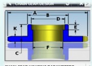
8 k3 e* q2 ^+ f+ i( I: l. z• Design a fixture for manufacturing* H" ~. i" S/ Q4 D* Z6 k k
When you design a fixture to use in a manufacturing operation, you must
# r9 F# Z, q; P( Y1 [know the state of the product in the manufacturing process in which+ l$ o5 J5 P- U$ j: j1 V
the fixture is consumed. You also should know the factory components9 I# d+ G5 f' w8 b: n/ Z) }
in which the operation is performed, and the relative positions of the
5 y2 w$ x. c8 X, s+ C9 A0 j7 [' Lin-process workpiece and the factory data.
( n/ I# E& b) R w' i" \/ T7 K8 o
" ^' O& q: C2 U) \" x$ E( J7 U3 |* y% W2 M$ l; w
|
|


 |小黑屋|PLM之家-专注工业软件生态建设,大模型CAD创新生态


 发表于 2015-8-4 11:00:14
 发表于 2016-4-25 22:46:28